Introduction
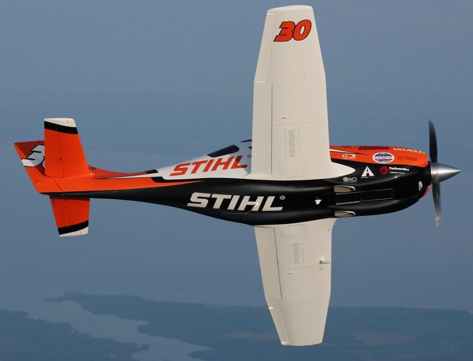
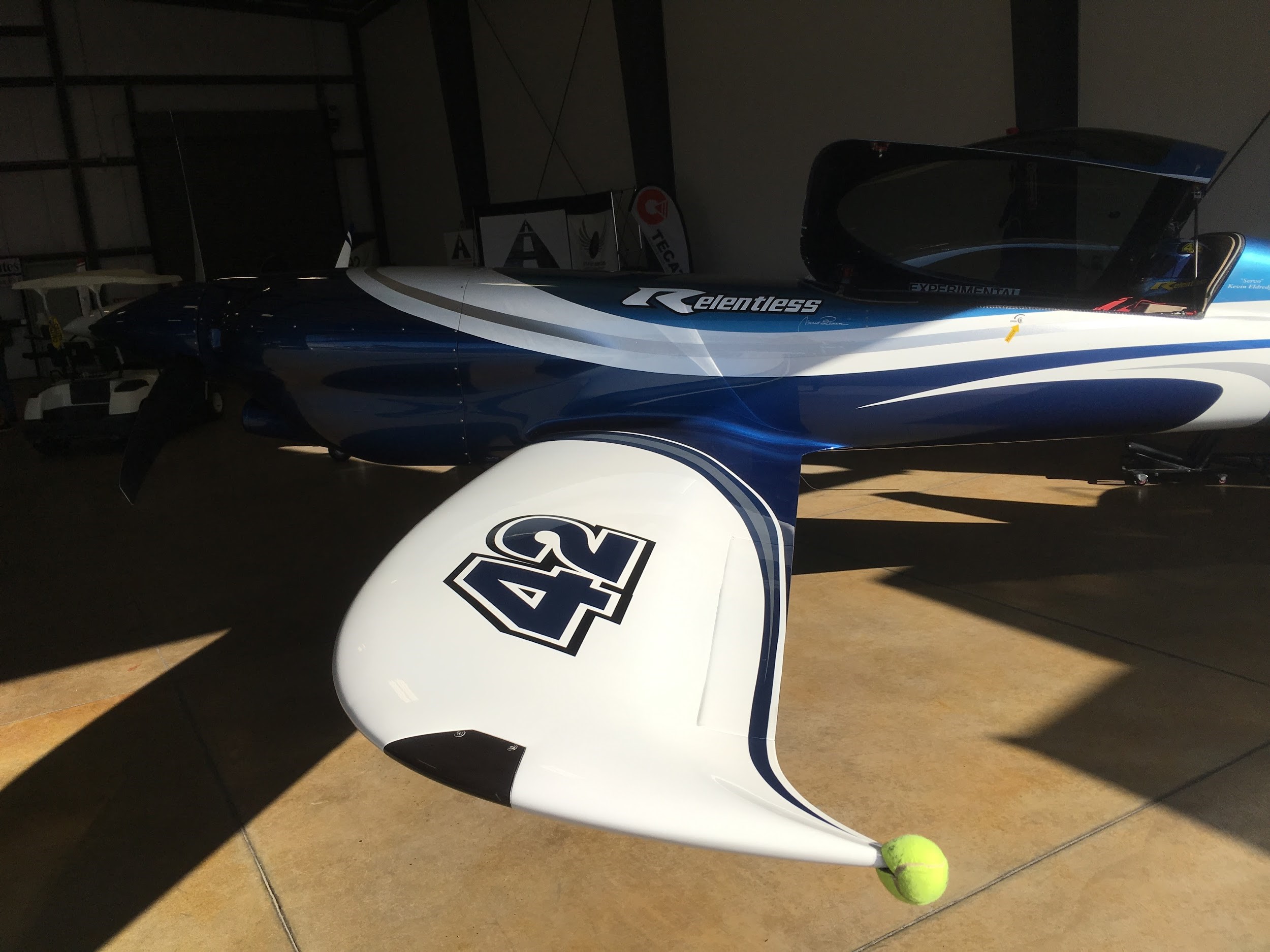
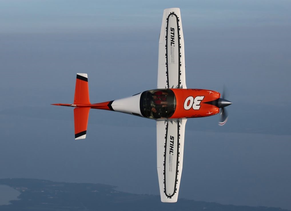
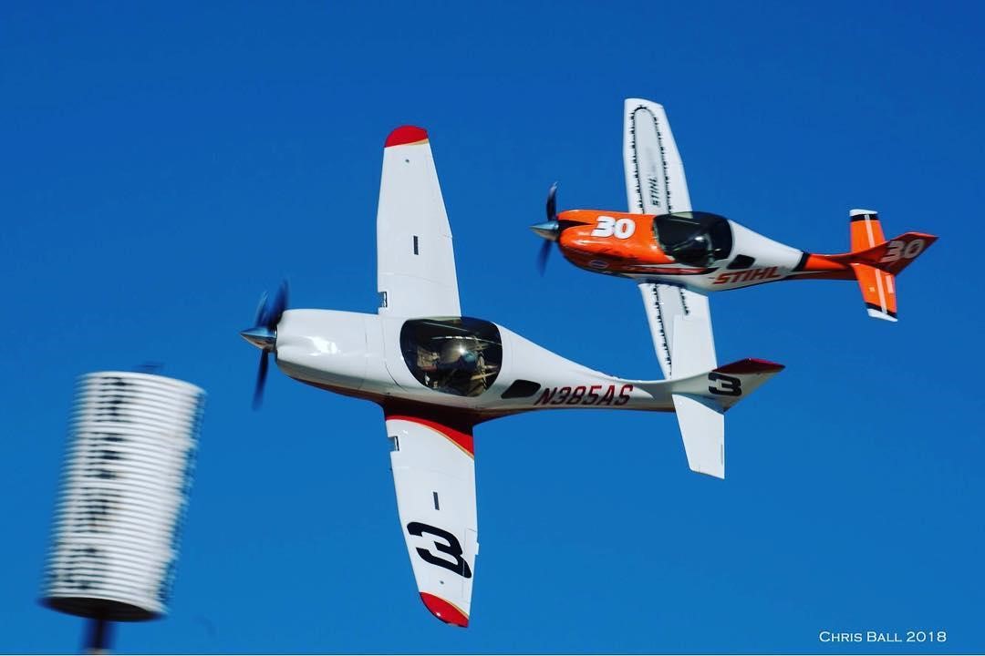
During the 2017 National Championship Air Races, team One Moment was pitted opposite Kevin Eldridge’s NXT “Relentless”. This meant we had the whole week to observe the sleek airframe. The wingtips in particular, have always caught my eye. The pointed shape is designed to reduce the drag caused by wingtip vortices. Looking back at Race #30, I wondered, “How hard could it be to reverse engineer the NXT tips and put them on the Legacy?”
Design
After unofficially breaking the 400mph mark (Note: not lap average) at the 2017 Air Races, preparations for the 2018 races began the day Andy returned from Reno. In October I reached out to Jon Sharp, asking what factors directed the wingtip design on the NXT. Jon was very encouraging and a wealth of information. He pointed me toward several NASA research papers on “sheared wingtips” which are referenced below. If you enjoy reading technical research papers, then they are worth a read, but our main takeaways were: 1) A curvy “sexy” wingtip isn’t always better, and if you aren’t careful they can create flow separation and more drag. 2) The sheared tip with the lowest drag has a sweep of 60 degrees. 3) Sheared tips can potentially reduce induced drag by 16%.
We also got in touch with Curt Burris, a Lockheed Martin aerodynamicist who worked on the F-22 along with a bunch of other projects I’m probably not allowed to know about. Armed with these resources we started drawing. Our goal was to minimize frontal area while increasing wing aspect ratio. Unfortunately, these criteria tend to conflict and compete with each other, especially when the structural side of things comes into play.
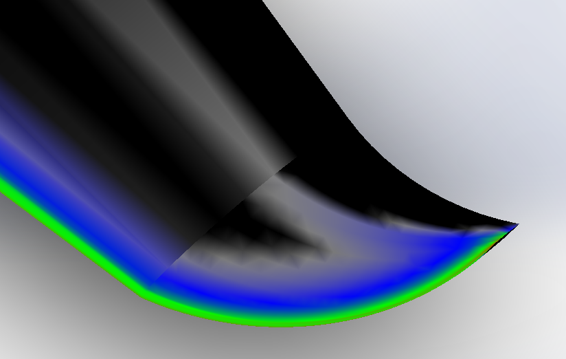
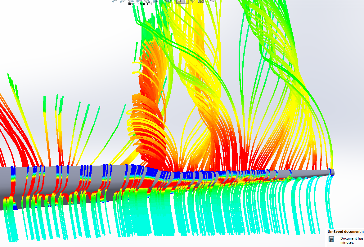
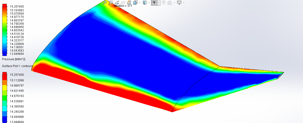
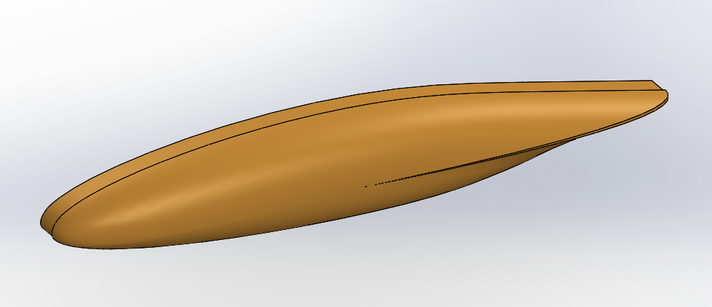
As can be seen, concepts ranged anywhere between a cosmetic copy of the NXT and the sheared tip designs from the research papers. Rob Stocklosa, another team member who helped CAD the custom turbo inlets on the cowling in 2015, modeled and ran CFD simulations on dozens of designs. Curt would review those CFD results and highlight areas that needed more work. We would then make the necessary changes and start the whole process over again.
If you’ve done any amount of writing, you’ve probably come across a section that doesn’t work. You rearrange the words, move the whole section around, but it still doesn’t sound right. So, in a fit of frustration, you delete the whole section (I did this several times while writing this report). Well six months into the design process, that is pretty much what happened to the wingtips.
Now if you’ve looked at any of the winning unlimited racers in the past 40 years, clipping the wings might seem like a no brainer, but there is real risk that clipping the wings will make an airplane slower.
Obviously having less frontal area and surface area means less drag and that’s why racers like Phantom have a tiny canopy and a skinny fuselage. But we were concerned the stronger vortices of a clipped wingtip would counteract any gains from the reduced area.

(wikipedia)
Induced drag comes from air wanting to reach the lowest pressure state possible (basically air is lazy). In the case of a wing, high pressure air under the wing normally reaches the low pressure area above the wing by flowing across the airfoil. This pressure difference creates lift. At the wingtip, however, it is easier for the high pressure air to curl around the end of the wingtip rather than flowing across it (again, air is lazy). This vortex disturbs the flow over the wing and reduces lift. With less lift, you must increase your angle of attack and that creates drag. And because a wing cannot be infinitely long, this will always happen as an “induced” byproduct of lift.
This becomes even more important at high angles of attack and G loads because you are making it easier for air to spill around the wing rather than flow over it. This is why many of the airplanes in Red Bull Air Race have winglets.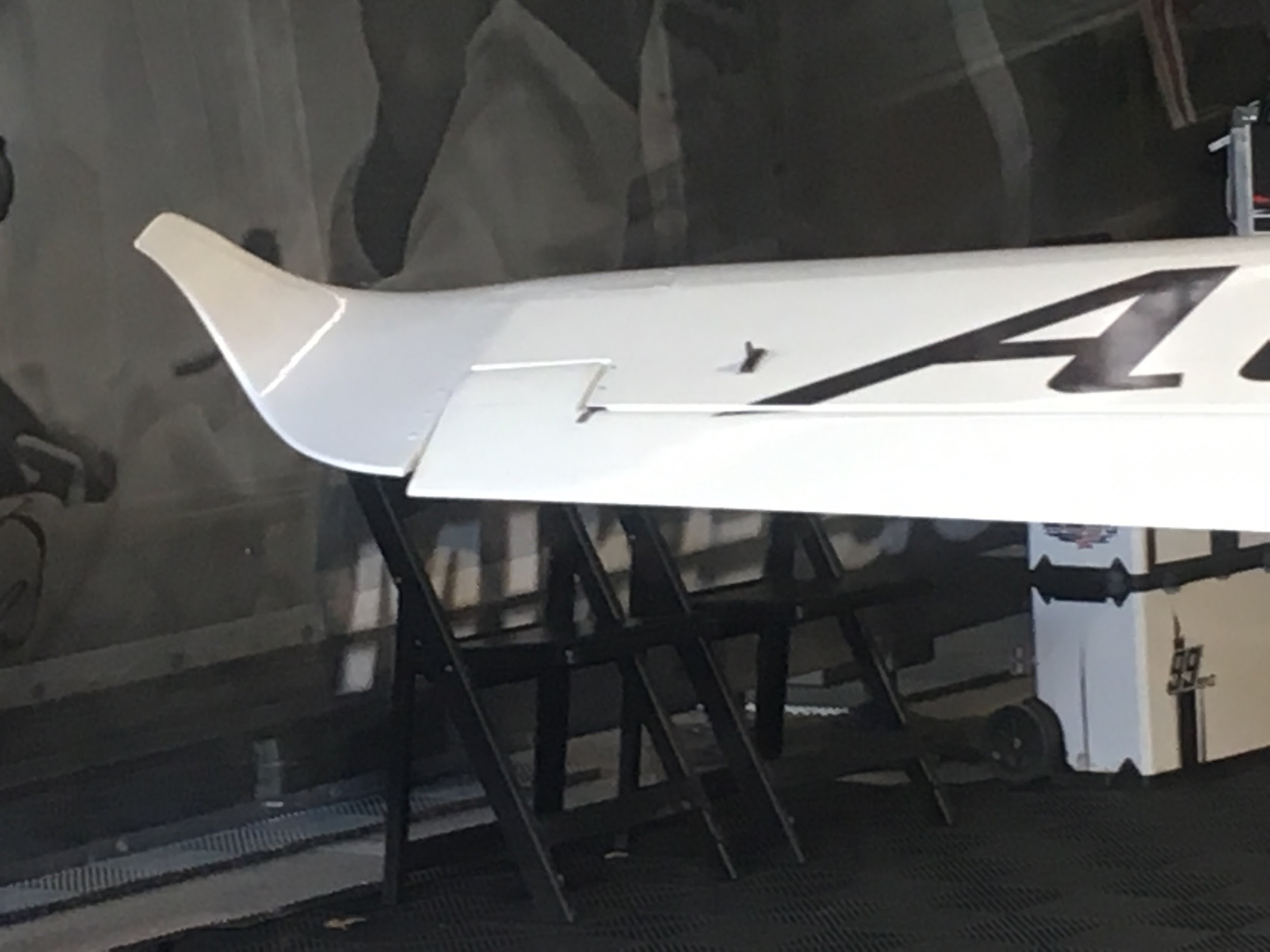
But when you look at the wingtip on Strega all you see is a rounded cap and a small wing fence for the aileron.Why are they completely different?
Again, induced drag is created from lift. When you look at the equation for lift, you find it is proportional to the velocity squared and lift coefficient (which is proportional to G forces). Therefore, the faster you go and the fewer Gs you pull, the less induced drag you will have.
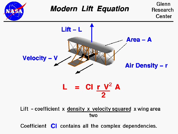
(NASA)
Strega has a much higher velocity than the Red Bull planes and isn’t pulling as many Gs. Relatively speaking, Strega’s wing doesn’t need to generate much lift to stay airborne. Therefore, at Reno the induced drag is not a big concern for us, and even though the induced drag slightly increases from clipping the wings, it is outweighed by the drag savings from a smaller frontal area.
Analysis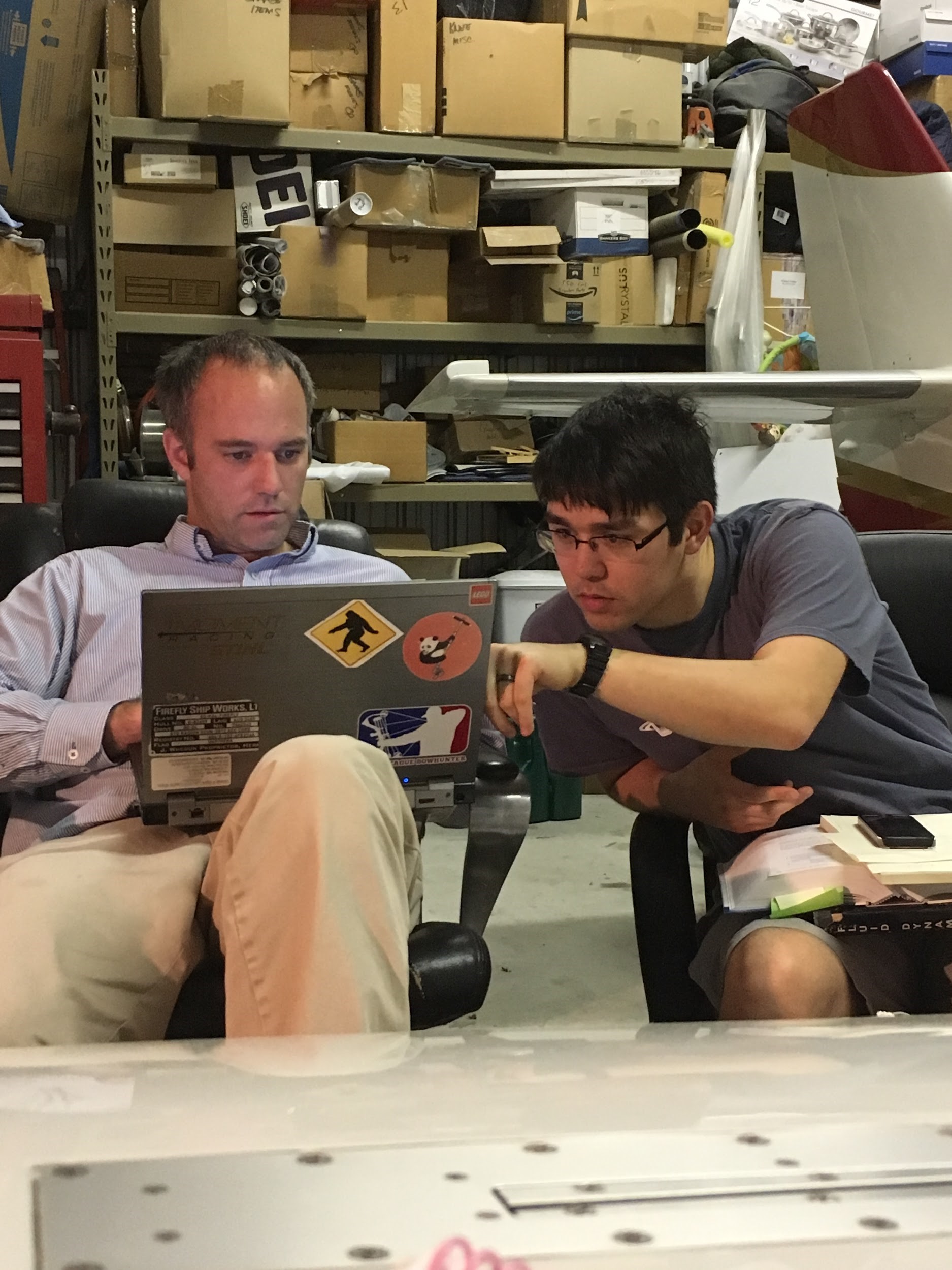
We pitched clipping the wingtips to Curt and after looking at our G force data from last year, he said it was worth pursuing. With more direction from Curt, we recorded the Legacy’s wingspan, surface area, race weight, air density, reynolds number, and more. We fed all of this data into a spreadsheet and calculated the total drag for 1 lap.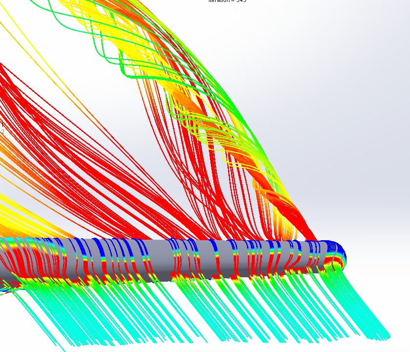
The clipped design cuts 2 feet off the wingspan and eliminates 590 square inches of surface area. We then fed that data for the clipped wingtip back into the same spreadsheet and repeated the process. When we compared the results the clipped wings were 5 knots faster.
We presented our calculations to Curt, and finally, after months of iterations and CFD runs, Curt was satisfied. “Knock em off”
Fabrication
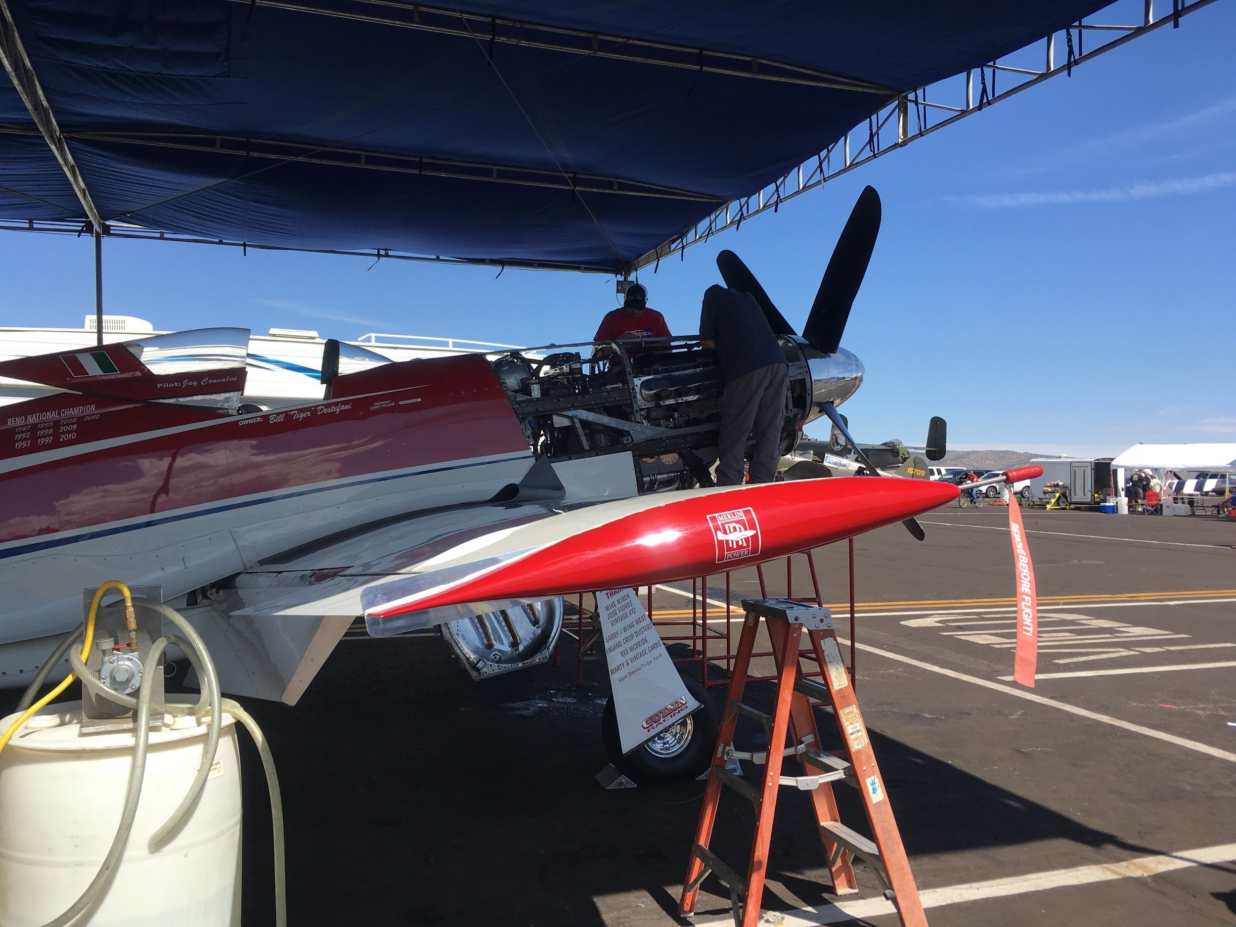
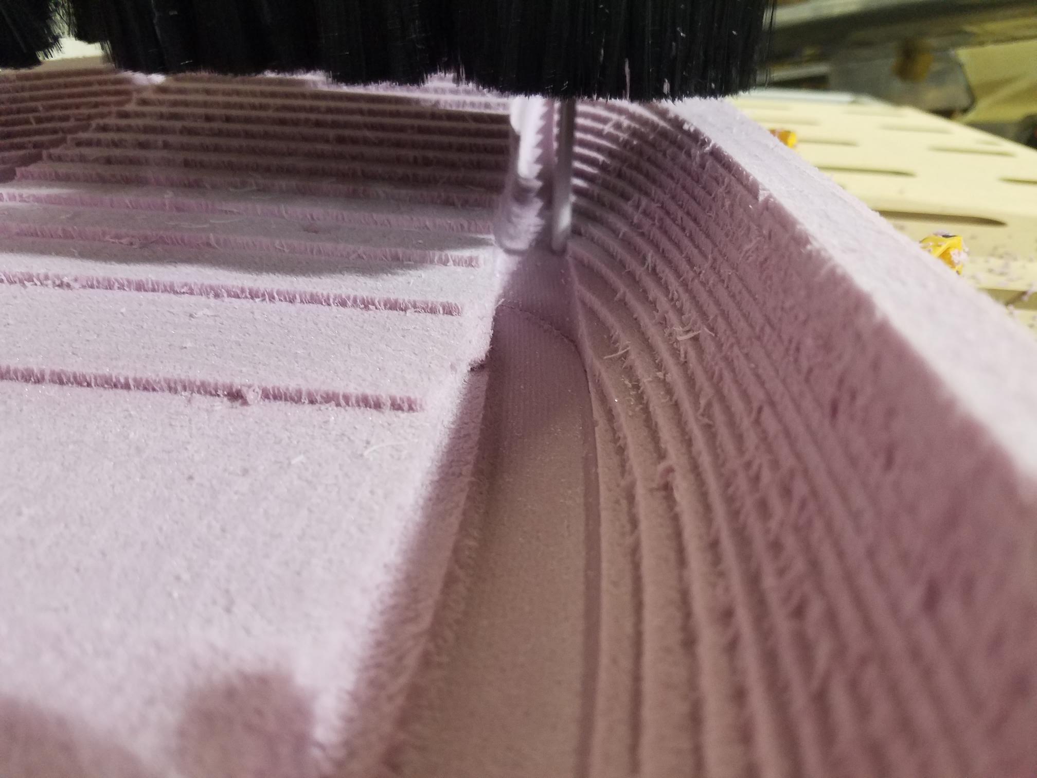
With the CAD done, along with the math to back it up, we reached out to Tom McNerney (Race #55 “Unleashed”), who cut the molds on his CNC machine and did the carbon layups.
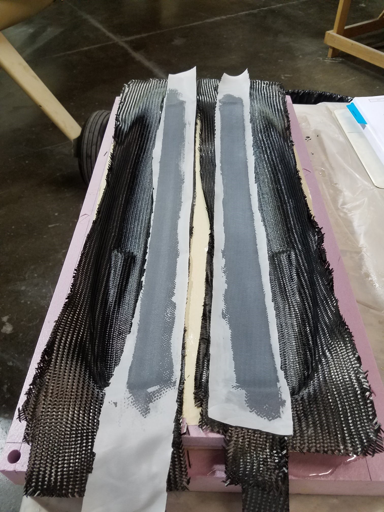
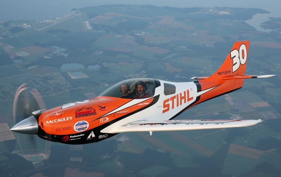
Tom and Andy met up at Airframes Inc. where Race #30 was being prepped for the new paint scheme. The stock tips were cut off just outboard of the fuel tank leaving enough room for fasteners and internal flange. Once the wingtips were fit up, they were layered with microballoons and sanded flush with the wing.
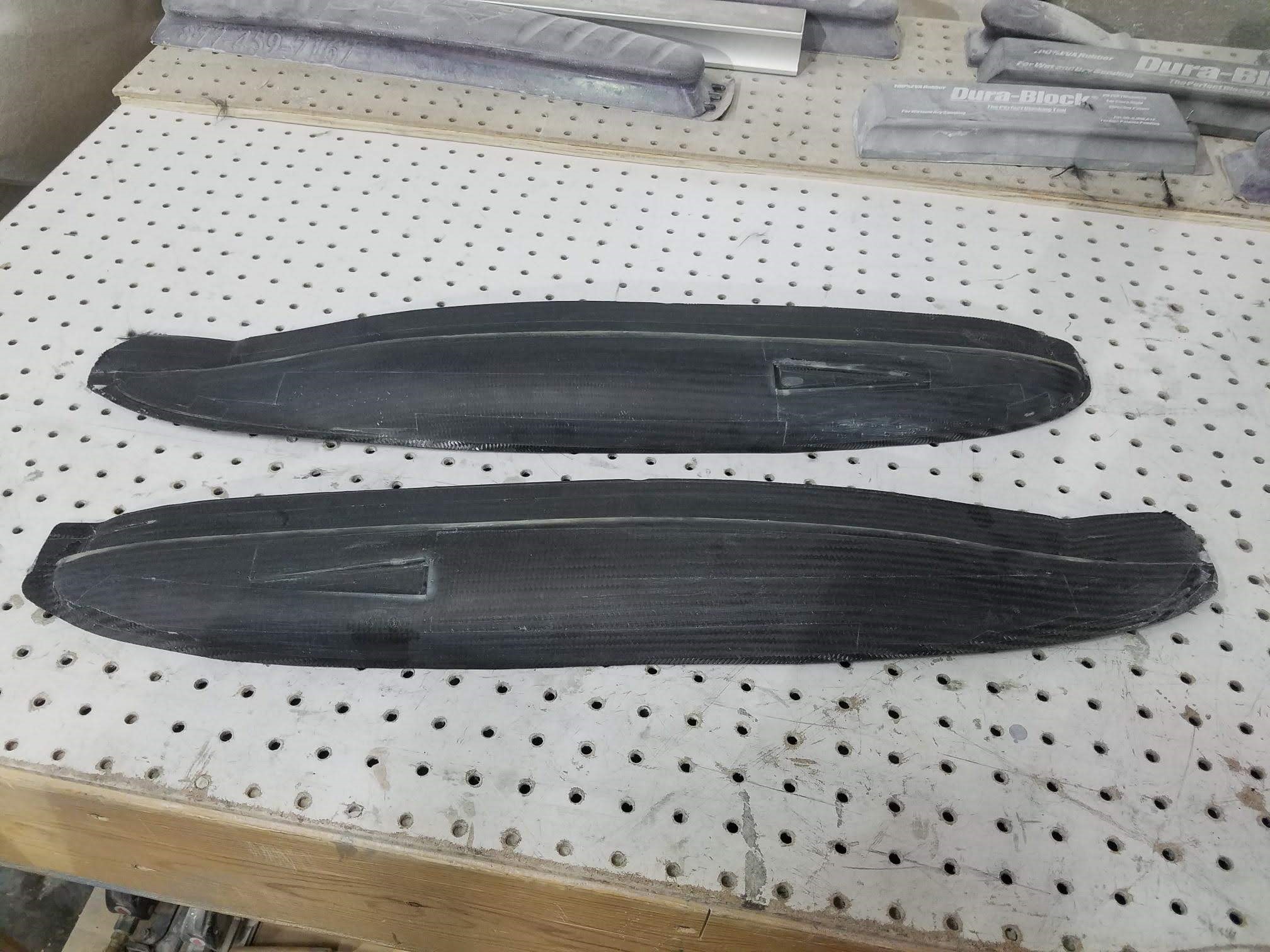
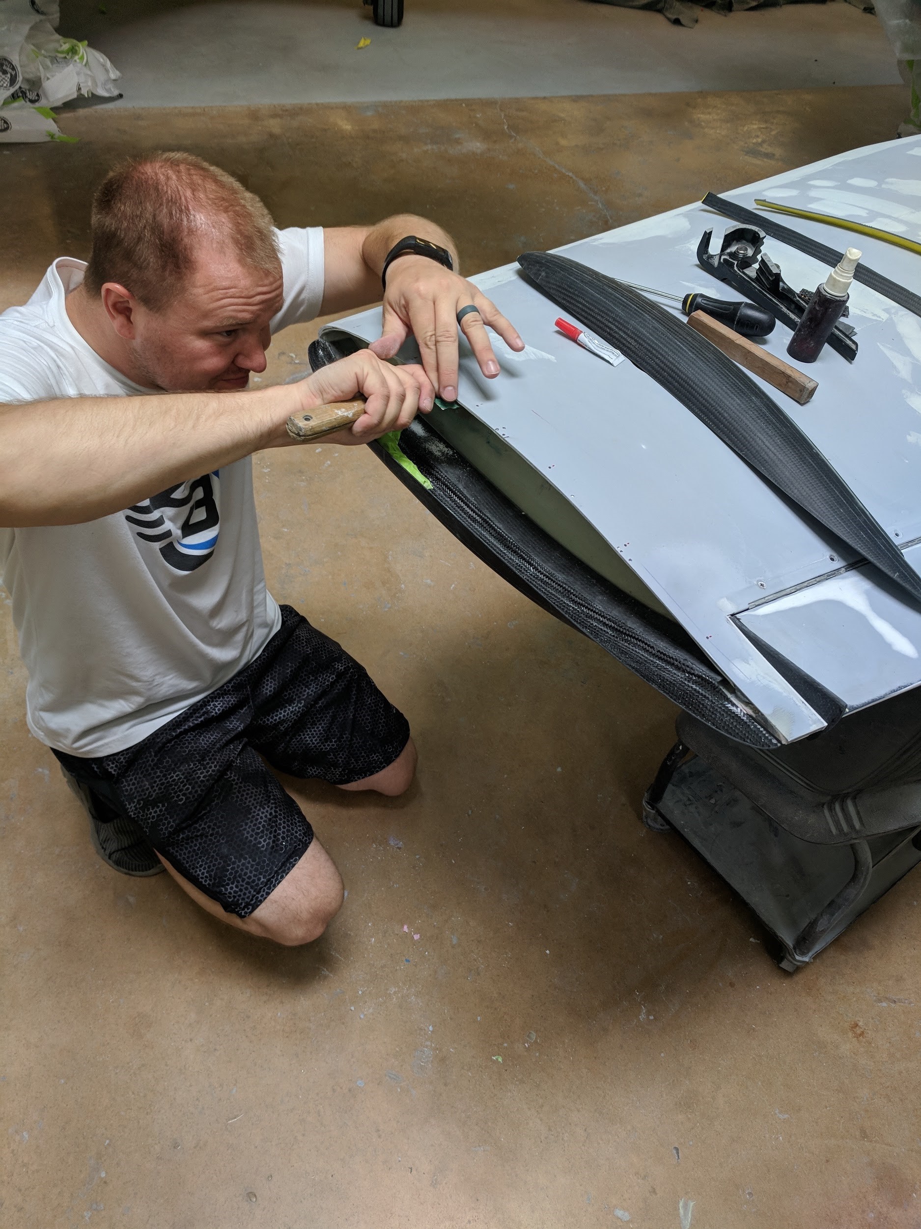
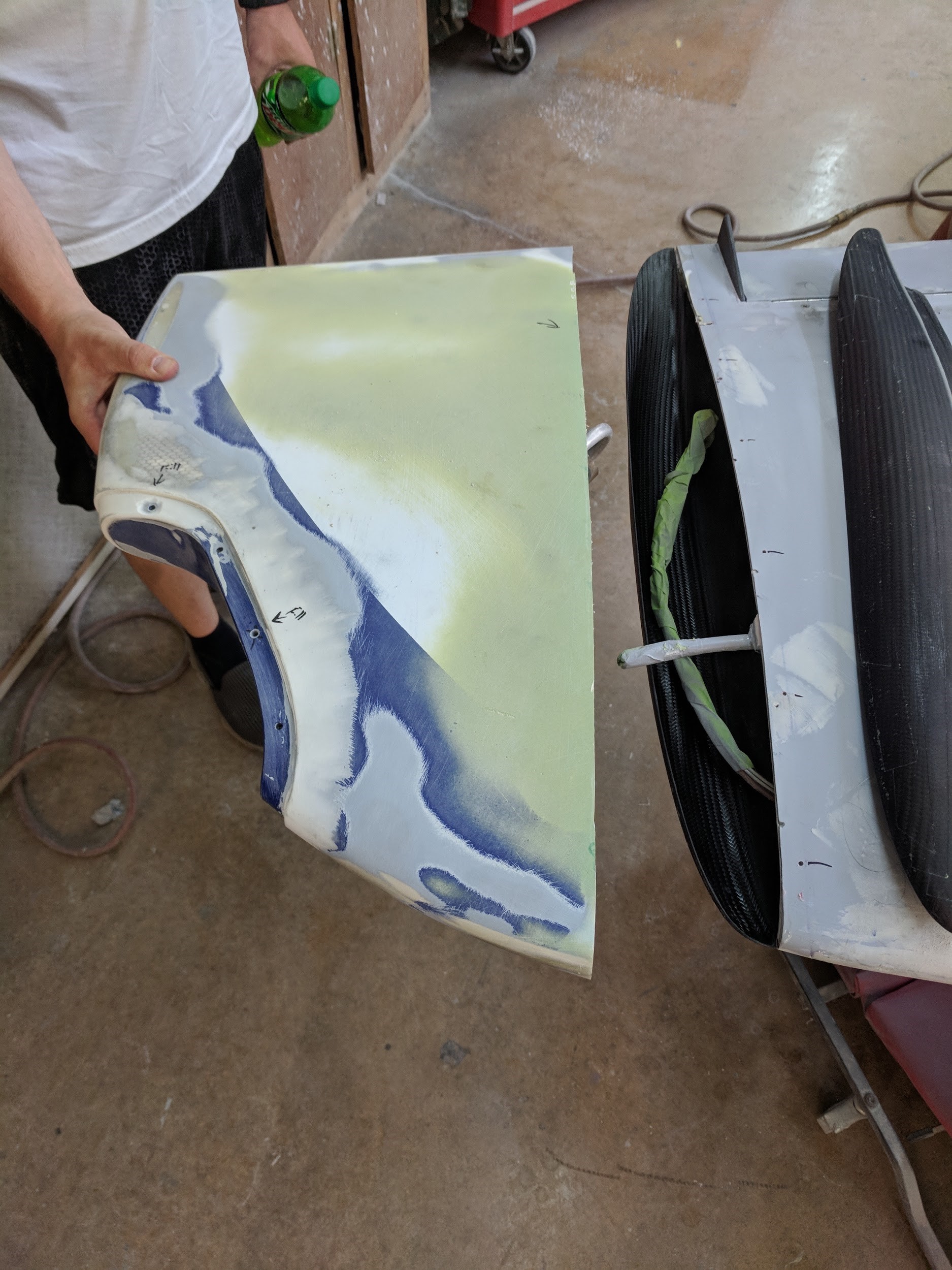
Finally, with the new wingtips finished, an internal flange was bonded into the stock wingtips, same as the clipped tips, so that the two sets could be interchangeable. Finally, it is worth noting that once the CAD was nailed down, fabrication and installation was complete within 7 days.
Testing
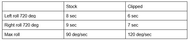
Once the plane was back from the paint shop we needed data to check that our calculations were in the ballpark. Roll rate was tested by timing how long it took to perform two consecutive rolls. For both left and right hand, roll rate increased by 33%
Slow flight was tested to 80KIAS without any sign of buffet or stall with pilot and half fuel (Appx 2200lbs). On landing, Andy did notice the plane would not float in ground effect, but was otherwise satisfied with the performance.
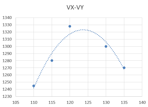
 Vy climb testing was performed in accordance with AC 90.89, with power at 30” MAP and 2600 RPM. The climb was initiated at 4000 ft, with the 1 minute timer set at 5000 ft. Tested IAS speeds were from 140KIAS to 100KIAS flown at 5 knot intervals. The climb data was plotted and Vx determined to be 123 KIAS.
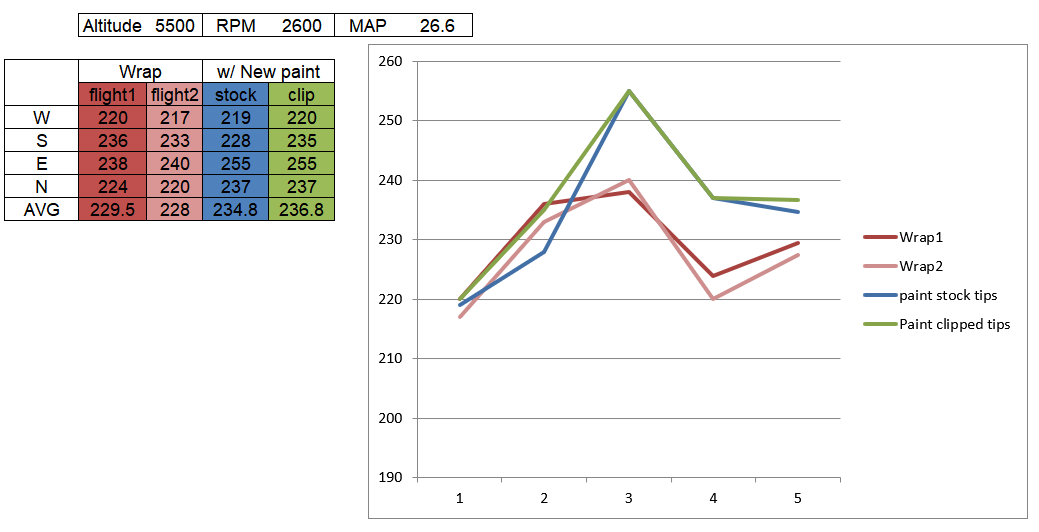
For cruising speed, Andy flew a test square at 5000ft AGL. This test was performed before and after the new paint scheme, with the stock wingtips and the clipped ones. The breakdown of the results indicate we gained 6 knots from paint and bodywork and another 2 knots from the clipped wingtips. When we plugged the above power settings and flight data back into our spreadsheets, the 2 knot prediction was spot on, giving us more confidence in the predicted 5 knots at race power.
Reno and concluding remarks
 With testing concluded, we swapped to the stock wingtips for the cross country flight to Reno. Swapping out both tips, taking care that the check valves for the fuel vents are oriented correctly, takes about a half hour. The clipped tips were installed Saturday night, and flown the rest of the week, without any issues.
If this seems like a lot of work for 5 knots, it was. It was an incredible effort by a group of amazing people, and seeing Race #30’s clipped wings rounding the pylons at 402.7 mph proves it was all worth it.
– “Young” Thomas
 References
1) P. M. H. W. VIJGEN and R. E. Mineck. “Wind-Tuennel Investigation of Aerodynamic Efficiency of Three Planar Elliptical Wings with Curvature of Quarter Chord Line”, NASA Technical Paper 3359 (1993)
2) P. M. H. W. VIJGEN, C.P. VAN DAM, and B. J. HOLMES. “Sheared wing-tip aerodynamics – Wind-tunnel and computational investigation”, Journal of Aircraft, Vol. 26, No. 3 (1989)
3) D. NAIK and C. OSTOWARI. “Experimental investigation of non-planar sheared outboard wing planforms”, 6th Applied Aerodynamics Conference, Fluid Dynamics and Co-located Conferences
Tremendous work! Thanks for sharing.